Underground Construction Technology: bored piles and columns, jet-grouting, jet-columns, grouting, diaphragm walls, shoring of excavation, consolidation of foundation and foundation bed, jet-grouting curtain, micropiles, anchors, lining, waterproofing, bed drainage, dewatering.

The Multifunctional center "The Tsar's Garden" under construction is located in Moscow historic center opposite the Kremlin between Moskva River and Vodootvodny channel on the area which appeared after demolition of obsolete low-store houses having no architectural or historic significance. The construction site is limited by Sofiiskaya Embankment from the northern side, Bolotnaya Street - from south, existing buildings - from west and Bolshoy Moskvoretzky Bridge - from east. The business centre consists of three buildings independent in their infrastructure and forming a complex of an impressive size about 220 m long and 47 m wide, floor area - 83500 m2. Aboveground sections of the buildings comprise 9 stores with a total area over 47500 m2, and underground sections of 4 stores, over 36000 m2.

The object is constructed in the area of partially filled Moskva River flood land.

Geological composition of the area is as follows:

Kremlin view from construction site Inspection of test jet-columns Consolidation of foundation of neighboring buildings by reinforced jet-columns Construction of permanent diaphragm wall. Trench excavation Construction of permanent diaphragm wall. Panel concreting Construction of temporary diaphragm wall. Placing of reinforcing cage Construction of permanent diaphragm wall. Placing of reinforcing cage Construction of bored column. Hole boring Construction of bored column. Bringing reinforcing cage on to placing point Construction of bored column. Placing of reinforcing cage in hole Construction of bored column. Preparing of reinforcing cage for centering Construction of bored column. Concreting Construction of bored column. Geologic survey at column foot - core sampling Construction of bored column. Flushing of column foot, forming of widened column foot by jet hydro boring Execution of horizontal jet-grouting curtain Construction of enclosing structure of pit for pass-through communication channel. Execution of vertical jet-columns Construction of enclosing structure of pit for pass-through communication channel. Execution of inclined (anchored) jet-columns Finishing of jet-columns of pit enclosure for pass-through communication channel Cut-and-cover pit for pass-through communication channel Prepare enclosing structure of pit for pass-through communication channel for waterproofing Building 1. Installation of form on ledgers before concreting of slab at level 0.00 m Building 1. Construction of floor slab at level 0.00 m Building 1. Construction of floor slab at level 0.00 m along communication channel Building 1. Form stripping at floor slab of level 0.00 m Building 1. Reinforcing the suspended lift shafts Building 1. Grabbing soil during excavation of the 2nd tire of pit through opening in slab Building 1. Installation of form on ledgers before concreting of slab at level 0.00 m Joint between bored column and floor slab. Phase 1 of construction Joint between bored column and floor slab. Phase 2 of construction Joint between bored column and floor slab. Phase 3 of construction Joint between bored column and floor slab. Phase 4 of construction Building 1. Waterproofing of diaphragm wall at -1 Floor Building 1. -1 Floor in erection opening area Building 1. Loading soil removed through erection opening in excavation of the 2nd tire of pit Building 1. Simultaneous execution of structures of +2 Floor and excavation of the 2nd tire of pit Building 1. Execution of structures of +3 Floor Building 1. Execution of structures of +4 Floor Building 1. Execution of structures of +5 Floor Building 1. Soil excavation at the 4th tier of the pit in the ramp area Building 1. Execution of temporary soil drainage construction under foundation slab
  • 4-6 m fill up soil with remains of foundations of old buildings and a lot of wooden rotten piles;

  • 1-8.5 m alternating layers and soft-plastic loam and plastic sandy-clays with water-saturated sand layers;

  • 2.5-20 m water saturated middle-sized sand, clayey with gravel and silt sand with sandy-clays layers as well as underlaying coarse sand and gravel-crushed stones soil;

  • 2.5-7 m water-rich Perkhurovsky low strength limestone, eroded to gruss and dust, with quaternary sand admixtures and thin clay layers as well as fissured, low and reduced strength layers of limestone;

  • 6-7 m Neverovsky marly-clays with interlayers of marl and limestone, semi-hard;

  • underlaying Ratmirovsky water-bearing limestone and marl, fissured and low strength, their top layer eroded to crushed stones, gruss and dust.

    In construction site south part in progress of geological survey an old river bed was discovered where a 17 meter deep layer of water-resistant Neverovsky clay is completely diluted and underground water of underlaying artesian horizon join the water of abovelaying nonartesian horizon making single water horizon at 3.7-4.5 meter depth from surface.

    The Multifunctional center "The Tsar's Garden" construction is executed by combined method providing for simultaneous construction of underground floors of the buildings using "top-down" method and the superstructures floors according to "down-top" method.

    The complex is constructed in three stages and in a sequence in order to satisfy the priority of interests of investors and tenants: first, Building 1 on the side of Vodootvodnoy channel, then Building 3 on the side of the Moskva River and at the final stage Building 2 between both constructed buildings.

    The works are executed in the following sequence: (FLASH-presentation: The common technology of the Multifunction complex construction, 728 kb)

    Prior to main works commencement the neighboring buildings standing close to construction site were consolidated in their foundations by soil-cement reinforced columns by "jet-grouting" method (DWF-drawing, 14 Kb).

    All secant jet-columns are 80 cm in diameter, with an average spacing of 65 cm, and reinforced with steel bars or pipes to reach the required bearing capacity.

    Supports for the structures of buildings under construction are the perimetral diaphragm walls and intermediate bored columns allowing to literally speaking suspend their aboveground eight to nine floor parts along with lift shafts and stairwells over pit deepened below.

    No limitations as far as prior construction of superstructure levels over underground levels were included in this project. Rather it was all the way around when the sooner the aboveground floors were constructed the more additional load on pit and the less is the value of deformations of surrounding soil masses and structures being executed.

    Geomechanical calculations undertaken by us only prove this:

    Displacements along axis X
    Displacements along axis X
    Displacements along axis Z
    Displacements along axis Z

    Permanent diaphragm walls, thickness 80 cm are made of concrete Â25 by Italian technique with keyed joints between standard panels 2.5 meter wide and non-standard closing panels - up to 3.49 meter wide. The cages of bearing diaphragm walls were shaped in order to allow the easy formation of horizontal grooves for the connection of the floor slabs of two upper underground stores and of the foundation slab. Such zones were strengthened by additional reinforcing bars.

    Temporary diaphragm walls, thickness 60 cm, separating each of construction three stages one from another, are made by the same method using lean concrete B7.5, and can be easily dismantled later. These walls were reinforced by reinforcing cages of new structure, specially developed by us for this purpose. To increase water resistance of the temporary walls a 30 to 50 mm layer of shotcrete provided with reinforcing mesh has been applied to the surface of the walls during the excavation.

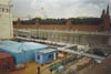
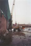
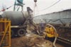
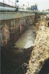
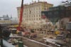
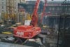
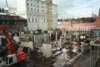
    Between temporary heating by-passes and permanent diaphragm walls along Bolshoy Moskvoretzky Bridge an underground communications channel was built, after its back filling the main driveway was made on construction site for the cargo vehicles, cranes and earth cutting equipment.

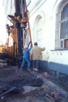
    As pit enclosure 6 meter deep under this channel we made use of vertical and inclined "jet"-columns, connected on top by in-situ reinforced concrete framing beam. The solution applied completely excluded temporary support of excavation pit and assured safety of works along operating heating line, where piping is quite sensitive to any displacements and settlements.
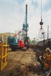
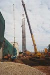
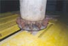
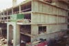
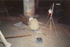
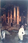
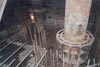
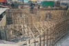
    Bored columns, diameter 72/120 cm of Â30 concrete, without which the project could not be implemented, have been constructed from site surface as permanent bearing structures not requiring any further strengthening or build up, except painting or decorative cladding

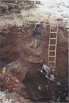
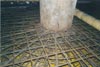
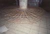
    The accuracy of columns construction (inclination from vertical line not to exceed 1:500) was achieved by using own gravity force of whole reinforcing cages, diameter 720/980 mm while their centering in holes, diameter 1.2 m, bored under protection of bentonite slurry. Tolerance deviation of column caps with account to design of their joints with underground floor slabs and foundation slab has been achieved ± 100 mm.

    Every reinforcing cage contained one guide-pipe in order to allow the execution of a core boring under the column bottom for a subsequent accurate geological investigation to check the bearing capability of each single column. The cage also contained two pipes for additional injection of cement grout into the foot. 14 main operations made the whole technology of bored column construction: (FLASH-presentation: The technology of bored column ñonstruction, 219 kb)

    For jointing of bored columns with underground floor slabs principally new, unified by design, simple and reliable joints were developed providing reliable operation at all construction phases, and being fire-resistant in operation of underground constructions.

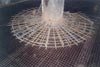
    A horizontal jet-grouting curtain was made with the purpose of limiting water infiltration inside the pit during construction of Building 1 in the old river bed area where Neverovsky confining clays layer were not present. This jet-slab was executed at 20 meter depth from the working level by "jet-grouting" technology, has area over 1500 m2 (DWF-drawing, 104 Kb).

    This jet-grouting curtain allowed to complete the "zero-cycle" of Building 1 only with a perimetrical drainage ditch. The water inflow from all jet-slab area did not exceed 40 m3/h including water leaking through the joints of the diaphragm walls panels.

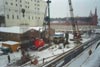
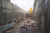
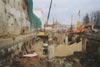
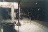
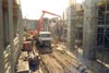
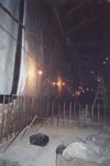
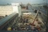
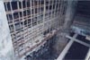
    Soil excavation in making pits 15 meter deep, for "zero cycles" of buildings is approved to be cut-and-cover excavation type at first tier and bulldozer excavation from second to fourth tier with permanent open-type pit water drainage. Tiers' height may be 3-4 m.

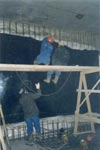
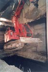
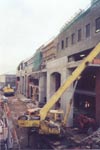
    Along diaphragm walls and bored columns soils are excavated by compact "Bobcat" excavators, blocks of limestone are broken down by the same excavators with attachable hydraulic hammers. A perimetrical drainage ditch is dug at each excavation level to collect residual water in sumps with exhausting pumps operating at intervals when required.

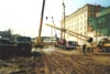
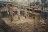
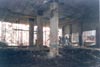
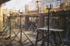
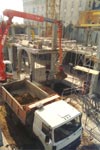
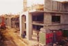
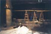
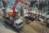
    From the second tier of excavation is carried out under protection of underground floor slabs constructed by "top-down" method, as the pit receives additional loading from aboveground levels structures, constructed by "down-top" method. Soils delivery from under the floor slabs is executed by clamshell excavator "Atlas-1704" through erection openings, left in floor slabs low-level aboveground parts of buildings.

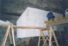
    In-situ bearing structures of Multifunctional complex are constructed of concrete grades Â30 and Â25. Following "top-down" method during concreting of zero cycle floor slabs forms support through wooden joists on plastic soils, their surface being dried by ground drainage and is consolidated by ramming 15 cm of crushed limestone.

    Starting from the second underground floor, the excavation and the construction of the underground structures are done in two stages: first in one half of the surface leaving a berm in the second half. Such sequence has been chosen in order to minimize the deformations of the surrounding ground mass and reduce negative effects on the neighbouring buildings and on the nearby bridge.

    Waterproofing of underground space is made of geosynthetics and is made following the closed and continuous scheme ("aquarium" type) not providing for a permanent drainage under the foundation slab.

    In order to ensure high reliability of waterproofing it is recommended to use its new structure with safety drainage layer and sectional systems of sealing of most vulnerable units.

    The structure of waterproofing system consists of following layers:

  • geotextile with density of 800 g/m2, as external filter-bed;

  • geomembrane 2 mm thick from very flexible and light-stabilized polyethylene (VFPE), the strips of which are butt-welded with contact hot-air- or extrusion-method. All welded joints are 100% tested for continuity;

  • "Tensar" geonet 6.3 mm thick from polyethylene, forming a safety internal drainage layer;

  • geotextile with density of 550 ± 50 g/m2, as protective layer and internal filter-bed;

  • polyethylene film 0.16 mm thick that prevents penetration of safety drainage layer and internal filter-bed by cement milk during execution of cast-in-place reinforced concrete protective walls.

    The reinforced concrete protective walls have 30 cm width and being designed to bear full-scale hydrostatic pressure. (Russian version, File PDF, 1076 Kb)

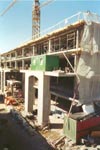
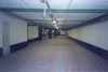
    The combined construction method allowed to construct an eight-floor Building 1 with four underground floors during 12 month only, same construction period is planned for Buildings 3 and 2.

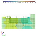
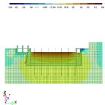
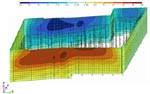
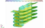
    Structures' economical nature is due to conducted 3D static computer calculations with account to redistribution of stresses and deformations in progress of construction and operation
  • Displacements isofields by Y (in mm) in diaphragm walls of Building 1 in excavation of core of 3rd pit tire under protection of floor slabs at levels 0.00 and -4.20 m. Stresses-chart by My (in tm/m) in the inner walls and ramps at Building 1 operation stage.

    Publications…

    Patents…

    Drawings catalogue…
    Building 1. Temporary support in slabs openings in the ramp area Building 1. Execution of structures of +6 Floor Building 1. Removal of compact excavator from under the slabs after pit excavation was completed Building 1. Completion of building superstructure construction Joint between bored column and foundation slab. Phase 2 of construction Joint between bored column and foundation slab. Phase 3 of construction Building 1. Foundation slab construction in the area of suspended lift shafts Building 1. Construction of lift shaft pits in the foundation slab Building 1. Waterproofing of diaphragm wall at the -4 Floor ramp area Building 1. Waterproofing of diaphragm wall at the -4 and -3 Floors Building 1. Completed parking at the -4 Floor Building 1. Completed parking at the -3 Floor Building 1. Building facades - finishing Building 1, commissioned for operation Consolidation of foundations of building ¹ 34à on Sofiiskaya Embankment by jet-columns Sinking of reinforcing pipe of jet-column consolidating foundations of building ¹ 34à on Sofiiskaya Embankment Building 3. Cut-and-cover excavation at the 1st tier of pit Building 3. Installation of form on ledgers before concreting of slab at level 0.00 m Building 3. Reinforcing of suspended lift shafts Building 3. Installation of form ledgers before concreting of slab portion at level 0.00 m Building 3. Slab construction at level 0.00 m Building 3. Panoramic view of floor slab construction at level 0.00 m Building 3. Tower crane base construction Building 3. Tower crane is used in constructing of the +1 Floor structures Building 3. Installation of form on ledgers before concreting of slab last portion at level 0.00 m Building 3. Completion of slab construction at level 0.00 m Building 3. Commenced soil excavation from pit of the -2nd tier Building 3. Stripping of forms under slab at level 0.00 m Building 3. Delivering of earth cutting machines under slab at level 0.00 m Building 3. View under slab at level 0.00 m in lifts shafts area Building 3. Loading of soil removed through erection opening during excavation of the 2nd tier of pit Building 3. Delivering of portable drainage sumps Building 3. Construction of columns and walls at the +1 Floor Building 3. Construction of slab portion at level +4.80 m Building 3. Facade wall construction at +1 Floor Building 3. Execution of structures of the +1 Floor at erection opening area Building 3. Earth cutting machines delivered under slab at level 0.00 m Building 3. Clearing the support groove in diaphragm wall for the floor slab at level -4.20 m Building 3. Ramming of crushed stone underlayer prior to construction of floor slab at level -4.20 m Building 3. Construction of floor slab portion at level -4.20 m Building 3. Execution of structures at the +2 Floor Building 3. Installations of form on ledgers before concreting of floor slab at level -4.20 m Building 3. Reinforcing the suspended lift shaft of the -1 Floor Building 3. Waterproofing of bearing groove for the slab at level -4.20 m

    Autodesk, Inc.
           In order to view drawings in DWF format you need to download and install Express Viewer on your computer from AutoDesk site.
    Adobe Systems Incorporated       In order to read publications in PDF format you need to download and install Adobe Acrobat Reader version 4.0 or high on your computer from site Adobe Systems Incorporated.

    Main page

    Previous

    Begin page
    Copyright © 2001-2010 "Yurkevich Engineering Bureau Ltd." / All Rights Reserved

      Ðåéòèíã@Mail.ru     Rambler's Top100